| |
HRC Honda
450R Power-Up Kit Install Instructions |
| 1. |
Remove the seat and front & rear plastic
|
| |
|
| |
 Figure 1
 - Plastic Removed |
| 2. |
Remove the gas tank |
| |
-
Ensure the gas is turned off
-
Remove the screw holding the petcock
and remove the lever and fuel mark plate
-
Remove the hose from the bottom
of the tank to the carburetor, remove the 2 bolts
securing the tank, the two tank straps, and lift
the tank off
|
| 3. |
Remove the Protector, Tank Heat
Shield(the plastic piece below the tank) see Figure
2 |
| |
 Figure 2
 - Protector, Tank Heat Shield |
4. |
Loosen the hose clamp holding the white plastic snorkel
and install the HRC snorkel and retighten |
5. |
Remove the airbox lid by unsnapping the 4 metal retainers
and the two bails and install the new HRC lid. Installation
of the mud flap is optional. |
| |
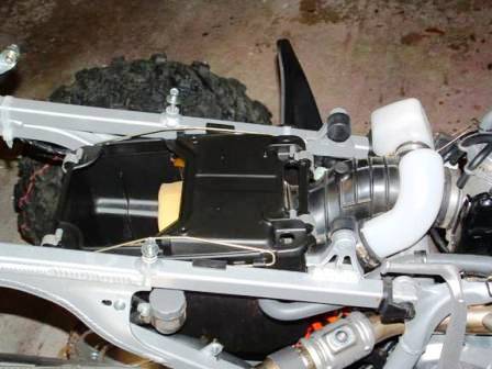 Figure 3
 - HRC Lid & Snorkle
Installed |
| |
|
| |
 Figure 4
- HRC Lid, Snorkle, and Optional
Mud Flap
|
| 6. |
Remove the 3 bolts holding the muffler
end cap on and slide out the core and old gasket.
Install the new gasket and HRC end cap and tighten
the bolts to |
7. |
Disconnect the 3-way breather joint from the crank
case, air box, valve cover and replace with the HRC
joint. |
| |
 Figure 5 -
 3-way Breather Joint |
| 8. |
Remove the 4 screws on top of carburetor and remove
the lid
NOTE - Installation
of the needle and main jet does not require removal
of the carburetor and only the loosening of hose
clamps and rotation of the carburetor 90 degrees
to install the main jet.
|
| |
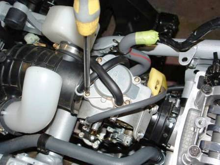 Figure 6 -
 Screw Removal |
| |
|
| |
 Figure 7 -
 Screws & Lid Removed |
9. |
Remove the two screws holding the arm set to the throttle
valve. |
| 10. |
Remove the Needle Jet. (A magnet
or needle nose pliers may help) and install the HRC
Needle with the retainer on the 3rd clip.
|
| |
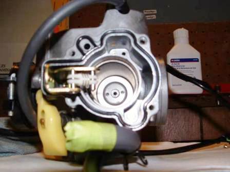 Figure 8 -
 Needle Removed |
| 11. |
Remove the 17mm bolt on the bottom
of the carburetor. |
| |
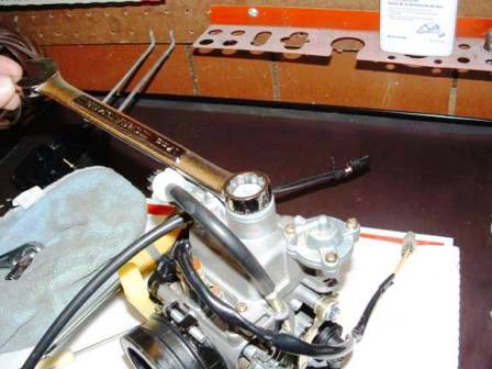 Figure 9 -
 17mm Bolt Removal |
| 12. |
Remove the main Jet with a 6mm
socket and install the HRC Jet and the 17mm bolt.
|
| |
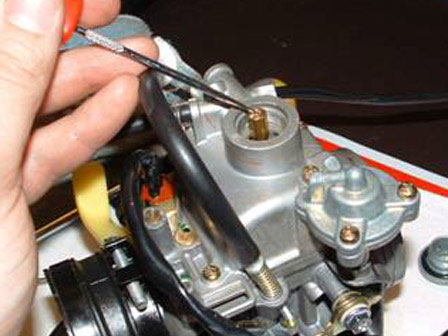 Figure 10 -
 HRC Main Jet (185) Installed |
| 13. |
Turn the Air/Fuel mixture screw
(Pilot Screw) all the way in and turn it back out
2.5 turns.
|
| |
 Figure 11 -
 Air/Fuel Pilot Screw
(Red Arrow) |
14. |
Remove the Spark Plug boot and
the Spark Plug. |
15. |
Remove the 3 bolts holding the valve
cover on and remove the valve cover. |
16. |
Remove the Crankshaft Hole Cap to
set the motor to Top Dead Center (TDC). TDC is achieved
when the two marks align |
| |
 Figure 12 -
 Remove Bolt to Align
Marks to TDC |
| 17. |
Once you have achieved TDC (you
can do this by moving your R forward in gear) you
need to secure the cam chain to the sprocket with
two large Zip Ties |
| |
 Figure 13 -
 Timing Chain Zip Tied |
| 18. |
Remove the two Allen head bolts
holding the sprocket to the camshaft. I found this
to be very difficult as they are secured with lock-tite.
Get a good pair of leather gloves and one person needs
to grab the sprocket and hold on for dear life. Person
number two needs to insert your Allen wrench and tap
it with a hammer to break them free |
| |
 Figure 14 -
 Cam Sprocket Allen Bolts |
| 19. |
Cam Chain Tensioner…there
are different thoughts on removal of this. Here is
what I did and I found it very simple. Take the end
bolt out of the tensioner and insert a small flat
head screwdriver. Turn the screwdriver clockwise until
it stops. All of the tension should be removed from
the chain and you can slide the sprocket off. Do not
let go of the screwdriver! Ease it back turn by turn
until it is free…it is spring loaded |
| |
 Figure 15 -
 Insert flat head and
turn clockwise to release tension |
| 20. |
Remove the four bolts holding the cam assembly.
NOTE: At this
point I would recommend you check the clearance
on your valves. I wish I would have checked mine
before I removed the cam. It is not necessary but
I wish I would have known.
|
| |
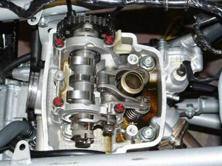 Figure 16 - Remove these 4 bolts
|
| 21. |
Steadily lift of the cam assembly
taking care not to drop any of the shims into the
motor. The assembly is positioned with bosses just
work it back and forth gently and lift up at the same
time and it will come off. If any of the shims come
off make sure you place them back on the correct valve.
|
| |
 Figure 17 -
 Shims |
| 22 |
Remove the decompressor bolt from
the cam assembly. I used a pair of vise grips but
some have used a vice. The vice grip method worked
wonderfully. |
| |
 Figure 18 -
 Remove this bolt (decompressor
) |
| |
|
| |
 Figure 19 -
 Here are the vise grips
I used (two person job) |
| 23. |
Remove the snap ring and the cam
shaft will slide out. |
| |
 Figure 20 -
 Remove this snap ring
and the cam will slide out |
24. |
Slide the HRC Cam in and reinstall the snap ring.
Apply Lock-Tite and install the decompressor bolt.
Torque decompressor bolt to: 18 lbf-ft.
NOTE: I used Lock-Tite
#243. It is an oil-resistant medium strength formula
(blue) readily available at the parts store. I consulted
Lock-Tite and my dealer on which product to use.
|
25. |
Reinstall the cam assembly and torque
the four bolts to 10 lbf-ft. |
| 26. |
Use a feeler gauge and check your
valve clearances.
Exhaust: .28 mm +/- .03
mm
Intake: .16 mm +/- .03 mm
|
| |
 Figure 21 -
 Checking one of the Intake
valves |
| |
|
| |
 Figure 22 -
 Checking one of the Exhaust
valves |
|
After you check all the valves you may need to make
shim changes. The easiest way to explain this is find
the correct thickness of gauge where it will slide in
an out with just a little tension or pressure on the
gauge. All of the shims are numbered according to how
thick they are. It sort of works backwards, if you can
properly fit a .220 mm (exhaust valve example) gauge
in then you are too tight even though it is a smaller
number then the required .28 tolerance. Therefore, you
add a smaller numbered shim to increase the amount of
space so the larger .28 gauge will fit. In the above
example if a .220 fits then you probably need to drop
.06 on the shim. So if the factory shim is a 215 then
you need to get a 209. It is not an exact science because
I was still .02 off from dead on .28 mm. I worked mine
a while with different shims and all the valves ended
up dead on. |
| 27. |
Check the clearance on the decompressor
arm:
Decompressor: .25 mm +/-
.02 mm.
|
| |
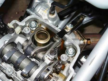 Figure 23 -
 Valve Clearance |
| 28. |
Mix your Molybdenum and motor oil
in a 50/50 solution and apply to the top off the shims,
lobes on the cam, rocker arm and lifters. I used Moly
Paste, my Honda dealer did not have anything else,
but it worked great. |
| |
 Figure 24 -
 Moly/ Motor Oil Solution
|
| 29. |
Ensure you are at TDC, turn the
screwdriver in the camshaft tensioner fully clockwise
and reinstall the cam sprocket and chain. Ensure the
alignment marks line up, (there are two marks on the
sprocket and two on the camshaft holder) apply Lock-Tite
and torque the sprocket bolts to: 14 lbf-ft.
You can now remove the Zip Ties |
| |
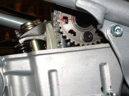 Figure 25 -
 One of the cam gear marks
(Another on the right side) |
| |
|
| |
 Figure 26 -
 Alignment mark on the
cam assembly (Another on the left side) |
| 30. |
Now begin reassembling your 450R.
Torque Specifications for Re-assembly:
Head cover torque: 7 lbf-ft.
Spark Plug: 17 lbf-ft.
Crankshaft Hole Cap: 11 lbf-ft.
|
| |
|